Still alive! I've been working on a model review for one of my clients, but I should have some time this week to push the action meta forward and catch up on the discussion groups.
- Leon
Tuesday, October 17, 2006
Thursday, October 05, 2006
Progress on the AL metamodel
The notes posted here have been a great help in getting the model started. I've made a lot of progress in the last few days. For now I am focusing on specification (non-runtime) information. Three specification subsystems are emerging - Action Blocks, Actions and Flow. Action Blocks is very small - it just captures the relationship among Operations, States and Services with Action Blocks and Parameters. Actions specializes what I've been calling "processes" into subclassifications. The action subclasses are then related to metamodel components like Class, Attribute, Event etc. For example, the Transmitter Action must specify an Event. By the way, I'm renaming "Transmitter" to Broadcaster to match the UML action semantics vocabulary. I keep referring to the UML terminology as much as possible. Finally, the Flow subsystem captures the graph nature of interconnected Actions. It consists of classes like Flow Type, Node Type, Pin, Process, Store and so forth.
Naturally, I will post my models once I have a reviewable baseline.
Naturally, I will post my models once I have a reviewable baseline.
Sunday, October 01, 2006
Linking and Unlinking
Processes (continued)
You may have noticed that relationship linking was not mentioned in the last batch of notes. It's not like I forgot them - alright I admit it - I forgot them. But I'm kind of glad I did as a bit of thought was required to sort out this seemingly trivial activity. And even then, I'm not sure I've got the best plan - but it helps to get things down on virtual paper. Remember that nothing in this blog is set in stone - just explorations to fuel the modeling activity. So feel free to register your comments if you think I'm going astray. Going astray is one of my specialties.
Linker Processes
A linker process creates or modifies links in a relationship. The link activity described in Mellor/Balcer's Executable UML (p. 120) is a primitive accessor that will be implemented as a core behavior in the metamodel. The primitive link activity takes two object references and a relationship name. (Though a perspective must also be specified to create a link on a binary reflexive association). That, notwithstanding, there is still work to be done before we can supply two distinct object references to our primitive linker. Assume that we route two object flows into a linker process. During run-time, any number of objects may be streaming along a given flow. Some object flows may come up empty and some may contain too many object references. How do we match up multiple object references from each flow? One approach would be to distinguish "single" object flows and stores from "many" object flows and stores. This is what is done in many executable UML action languages. Wouldn't it be cool though, if we could shift the burden of the one-many selection/store distinction away from the modeler to the underlying execution model? The downside is that we must imbue the action execution engine with the smarts to multitudinous disparity in a predictable way. In that spirit, here we go. These are the link activities processes that must be supported:
- association linker
- association unlinker
- generalized object creator (normal object creator redefined)
- generalized object eraser (normal object creator redefined)
- reclassifier
We start using the / symbol to separate a role or informal name from a defined element. So if we see something like 1 / object_flow, we know that the name or phrase left of the /, "1" in this case, is just an informal name whereas the element on the right has a definition somewhere in the action language notes. In other words, there is an object_flow named "1".
Association Linker
Links one object to another (or the same object) on an association.Flows In: { status } 1 / object_flow < 2 / object flow >
Flows Out: < association class / object_flow >
Specification: rnum
Let's explore each variation.
Binary non-reflexive
( Dog Owner - 1 - is owned by -- owns - 1..* - Dog )
The modeler connects two object flows to the linker. The active perspective will be automatically connected to flow 1 and the other to flow 2. For example, one object pool might be labeled lazy_dogs and the other new_owner. Each generates a seperate object flow into the linker.
Binary reflexive
( Aircraft - 0..1 - takes off after -- takes off before - 0..1 - Aircraft )
The modeler specifies which direction to link by routing the active perspective to flow 1 and the passive perspective to flow 2. This cannot be determined automatically, so it is up the modeler to set these as intended. For example, assuming that "takes off before" is the active perspective (arbitrarily in this case), the flow for aircraft_entering_queue would go to flow 1 and the last_in_queue flow would be 2.
Unary (symmetric reflexive) association
( Territory - 1..* -- borders )
Since the perspective is symmetric it doesn't matter which flow is 1 or 2. If, for example, we link Territory Brazil to Venezuela on "borders" it's means exactly the same as if we did the reverse.
Cyclic link
To link an object to itself on a binary reflexive or unary association only one input flow, object flow 1, is required. It is the same result as flowing two different reference to the same object on the 1 and 2 inputs.
Perspective Multiplicity and Flow Cardinality
Consider the 1, 2 object flow inputs into the association linker. Either object flow could be empty, contain a single object reference or stream multiple object references during run-time. Lets refer to the empty, single and multiple quantities of object references as the cardinality of the flow. How should the linker connect the objects from each stream given each possible mix of cardinality?The empty case is easily squared away. If at least one input is empty then no links can be made since we always link objects referred to in flow 1 with those in flow 2. The only exception is the cyclic link case mentioned earlier. In this case input 2 is not used and no link is made if input 1 is empty.
This leaves us with these flow cardinality combinations for inputs 1,2: (1, 1), (1, 2..*), (2..*, 1), and (2..*, 2..*). Before we can determine how to link the objects referenced in the paired flows, we need to know the multiplicity of the corresponding perspective of each flow.
First, a quick aside regarding association perspectives. In * UML, the "binary" in binary association does not refer to the class on each side. That is because, in the case of a reflexive binary association, there is only one class, e.g. Plane takes off after Plane. Instead "binary" refers to the two perspectives on the association, e.g. takes off before / takes off after. In the metamodel we needed a way to distinguish between each perspective. We could have used a generic label such as the A and B perspective but that's not very descriptive. Most of the time (in English, at least) we can distinguish the active and passive voice. For the perspectives "owns" and "is owned by", for example, we recognize "owns" as the active side. This rule doesn't always work. The perspectives "is before / is after" are both active. But this is a less frequent situation and we are no worse off than the A/B labeling solution.Now if we follow the convention of running the object flow corresponding to the active perspective into flow input 1 on the linker with the passiver perspective object flow going into input 2, it is easier to describe how the objects will be linked. In the table below we cross all flow combinations with all perspective multiplicities. Conditionality (0..1, 0..*) is removed from consideration so we are just looking at pure multiplicity in the leftmost column. So S means single (0..1 or 1) and M means many (* or 1..*).
| | | | Flow Cardinality (1, 2) | |||
| | | | 1, 1 | 1, 2..* | 2..*, 1 | 2..*, 2..* |
| Mult (a,p) | S, S | | one->one | one->one | one->one | { one->one } |
| | S, M | | one->one | one->all | first->one | first->all |
| | M, M | | one->one | one->all | all->one | all X all |
The plan is to link as many objects together as possible given the supply of object references. The normal (intended use) cases are highlighted in green. Possibly useful in, uh maroon? and shaded for those of doubtful utility. Let's look at the normal cases first.
The association multiplicity and flow cardinality matches in each of the normal cases.
Multiplicity (S, S) - Flow (1, 1)
A pair of object references arrives, one on each flow. The object referenced in flow 1 is linked to the object referenced in flow 2.
Multiplicity (S, M) - Flow (1, 2..*)
The single multiplicity corresponds to the single object flow and the many multiplicity corresponds to the multiple object flow. The single object referenced in flow 1 is linked to all objects referenced in flow 2.
Multiplicity (M, M) - Flow (2..*, 2..*)
Each object references supplied in one flow is linked to each object reference from the other flow to create a cross product. So active(1, 2), passive (3, 4, 5) would yield links 1-3, 1-4, 1-5, 2-3, 2-4, 2-5
In the next case, some object references may be ignored.
Multiplicity (S, M) - Flow (2..*, 2..*)
Each object referenced in flow 1 is linked to the next object in flow 2. This pairing continues until there are no more objects in flow 1. Any remaining objects referenced in flow 2 are dropped.
In the remaining cases, some object references will be ignored.
Multiplicity (S, M) or (M, M) - Flow (1, 1)
Since only two object references are delivered, there is only one linking choice. The two referenced objects are linked together.
Multiplicity (S, S) - Flow (1, 2..*) or (2..*, 1)
The single object referenced on either flow can only be linked once. Consequently, only one link can be made with all remaining object references dropped.
Multiplicity (S, M) - Flow (2..*, 1) or (2..*, 2..*)
Since only one object referenced in flow 1 can be linked, the first object referenced in flow 1 is linked to the first or only object referenced in flow 2. All other object references are dropped.
Multiplicity (M, M) - Flow (1, 2..*) or (2..*, 1)
The object referenced from the flow with cardinality 1 is linked to all objects referenced in the flow with cardinality 2..*.
Association Unlinker
An association unlinker breaks existing links on an association relationship. If there is an association class present, each corresponding association object will be removed automatically.Flows In: { status } 1 / object_flow < 2 / object flow >
Flows Out: None
Specification: rnum
Unlinking can be defined with or without targets specified. Use of object flows 1 and 2 vary depending on the type of association.
Binary non-reflexive
( Dog Owner - 1 - is owned by -- owns - 1..* - Dog )
Target specified
We can unlink one or more objects in one class from one or more specific objects in another class. Each set of object references is input in a separate flow. Object references form the active perspective will automatically be assigned to flow 1. For example, one object pool might be labeled lazy_dogs and the other new_owner. Each link that exists between a member of flow 1 to a member of flow 2 will be erased.
Target not specified
If we use only one object flow, all links to the referenced objects in that flow will be erased. Let's say we flow from an object pool named dead_dogs into the unlinker. Each link to an object referenced in dead_dogs will be broken.
A quick aside about unconditional constraints. We can see from the multplicity on the example association that a Dog Owner must own at least one Dog. In each of our unlink examples one or more dog owners could have been left dogless. To maintain data integrity, the modeler will need to specify some activity to either delete the owner objects or assign new dogs. Now, we may find a way to make this burden easier as we flesh out the action language. But that's going to require some serious analysis. So, for now, assume that no magic maintains unconditional integrity unless otherwise specified.Binary reflexive
( Router - 0..* - sends mail to -- gets mail from - 0..* - Router )
Target specified
The modeler specifies which direction to unlink by routing the active perspective to flow 1 and the passive perspective to flow 2. This cannot be determined automatically, so it is up the modeler to set these as intended. Let's say that we have a Router object C that both sends and receives mail from a Router object D. The active perspective should be "sends mail to". To unlink in the send direction, from C to D, the object flow with the reference to D ("sends data to" - D) must be 1 (active) with C on flow 2 (passive). If unlinking in both directions was desired, the "not specified" method is probably a better choice.
Target not specified
Only one input flow is supplied in this case. For example, to unlink any object sending or receiving from C, output a reference to C on one object flow into the unlinker. All links involving C on the specified association will be erased.
Unary (symmetric reflexive) association
( Territory - 1..* -- borders )
Target specified
Two object flows are required and assignment to 1 and 2 is arbitrary. Each object referenced in one flow is unlinked with any connected object referenced in the other flow.
Target not specified
Only one object flow is required. All links are broken to each object referenced in the flow.
Cyclic unlink (target specified is itself)
To unlink an object from itself on a binary reflexive or unary association only object flow 1, is required. It is the same result as flowing two different reference to the same object on the 1 and 2 inputs.
Generalized Object Creator
Our definition of creator from the previous post must be extended to accommodate the peculiarities of generalized/specialized objects. In a * UML generalization, a single object is represented by two instances, one in the superclass and one in a subclass. The creator must create both of these instances. The name of the subclass must be specified.If an object participates in more than one generalization, all participating instances must be inserted by into the metamodel by the creator. Consider the following arrangement of generalizations:
A <R1 [ B | C ], C <R2 [ D | E ], F <R3 [ E | B ]
Here we have three generalizations R1, R2 and R3 with superclasses A, C and F respectively. To create an object in this example model, a non-specialized (leaf) subclass must be specified. If we specify E, for example, instances will be created in classes E, F, C and A. For subclasses, our object creator both creates and links. Any initialization activity coordinated amongst the instances must be modeled explicitly. Only the instance creation/linking is automatic.
Multidirectional generalization requires the specification of one subclass per direction:
G <R4 [ H | I ], G <R5 [ J | K ]
The set of possible creation specifications are all combinations of non-specialized subclasses linked to a common superclass. So in the model example above we have: (H, K), (H, J), (I, J), (I, K).
One attribute flow per created super or subclass instance may be provided. (This means that the definition of an attribute flow in the previous post must be amended to include a class_name in the flow content. And since I can just do that now, I will. Done.)
Specification: 1{ non-specialized_subclass_name }
Flows In: { status } { attribute }
Flows Out: < object >
The output flow returns a reference to each specified subclass. References to the newly created superclass instances can be found using with a selector process traversing the generalization(s).
Generalized Object Eraser
We will now extend our eraser process so that it can handle generalizations properly. An object in a generalization, super or subclass, is represented by two instances. If an object participates in multiple generalizations there will be one more instance per additional generalization. Every one of these related instances will be eliminated by the object eraser.Referring back to the generalized object creator example models, let's say that we specify a reference to an instance of class F. Following instances must be erased: F, either E or B, A and if E then also C
The modeler must be careful to not specify deletion until all cleanup and coordination for every instance involved has been accomplished.
Flows In: { status } object
Reclassifier
A reclassifer migrates a subclass instance in a generalization to another subclass at the same level. This means that the original subclass instance must be erased and a new instance created in the destination subclass. Both subclasses must be at the same level in the same generalization. Based on our earlier model examples in the creator and eraser, you can probably guess that the activity doesn't necessarily stop there!Let's say that we want to migrate C to B. We must delete and unlink the D or E subclass under C (but keep the D/E superclass F intact. Then we delete the C instance, create a B instance and link the B instance to both the A and F superclasses. Any supplied attribute data can be used to initialized the values in B (B only since that is the only created instance).
Once again, it is the modelers responsibility to ensure that any coordination and cleanup activity in the subclasses to be deleted is completed before triggering the reclassification.
Specification: from_subclass_name, to_subclass_name
Flows In: { status } { attribute }
Flows Out: < object >
The output flow returns a reference to the newly created subclass instance.
Conclusion
Okay, that's all for now. I'm going to need some spicy indian food and bad television before getting back to the metamodel.
- Leon
Wednesday, September 27, 2006
Action Language Notes
Here are some rough notes on the proposed anatomy of the * UML action language. All semantic elements can be represented as text, a la SMALL, or as graphical symbols a la Scrall. For visualization purposes, graphical symbols are less restrictive than text statements. Eventually we will establish a clear connection between these elements and the corresponding UML 2.0 action semantics. For now though, we need to build something that works well, with a minimum of components.
A parser will yield the elements described here so, at this level, we don't care about notation or syntax. We do want to distill the essence of an action block specification so that we can build a machine that can execute any action block. Rather than build a full blown action language all at once, it is probably best to define the core elements and implement a primitive machine. Then, with some experimentation, we can extend or rethink the language to evolve something truely useful.
Ss the goal of these notes is sort out the concepts required to support the specification of action components as well as the run-time execution of those components in an action language interpreter. Whereas SMALL and SCRALL focus on syntax primarily, we need to sort out the underlying mechanics and integration with the metamodel. The next step will be to start modeling those concepts. Incremental versions of the action language metamodel will be posted at sourceforge for anyone interested.
Here are some questions we hope to answer:
We must also keep in mind that varying degrees of parallelism are possible depending on the target architecture. So we must be careful not to define structures that perform only in a sequential context.
Action Block
An action block is a bundle of action language associated with a state, class operation or service. Action language consists of nodes (processes and stores) connected by flows.
Every flow specifies at least one source and destination. The types and quantities of sources and destinations depends on the flow type.
Specification: Unique_id < Descriptive_name >
Specification: None
Source: [ object_pool | selector | creator ]
Destination: [ object_pool | transmitter | eraser | tester ]
Run-time content: { object_reference }
Uses:
Specification: class_name, 1{ attribute_name }
Source: [ object_pool | transform ]
Destination: [ object_pool | transform | tester | creator ]
Run-time content: { < object_reference > 1{ attribute_name:value } }
Uses:
When writing to specific objects during run-time, the following data is expected:
An attribute flow into an object pool containing only name:value pairs and no object reference will write all objects referenced in the pool to the same values.
The following data streams when reading attribute values from an object pool:
Here we see that each data item includes an object reference with at least one accompanying attribute name, value pair. The syntax above does not suggest any particular implementation. You don't have to send an attribute name with each value. But there must be some mechansim to ensure that the attribute of each value in an attribute flow can be determined during runtime.
Specification: None
Source: [ value_store | transform | service ]
Destination: [ value_store | transform | tester | service | selector ]
Run-time content: value
Uses:
A status flow communicates a boolean condition to a downstream process to effect or negate execution. If a status flow is enabled during run-time, the condition is enabled. A process may not execute until all input control flows have been enabled and all input data is available.
Before considering the run-time content of a status flow, we need to understand how flows are managed in general. Every flow, regardless of type, starts off in an "inactive" state. This means that the flow has not yet been populated with any data. Once a flow is populated by whatever process or store provides its input, the flow enters the "activated" state. This means that data is now available. The content of an "active" flow may be "empty". (An object selection that returns no references, for example, would populate an object flow with zero object references). Once all data in a flow has been consumed, the flow enters a final "consumed" state.
When a status flow leaves its "inactive" state, it must be set to either true or false. Any process receiving the false input will not execute. True means that the process may execute. The name of the flow reflects its condition when set. Let's say the name of the flow is "Max Pressure Exceeded" and it feeds into a process named "Close valve". The process may execute only if the value of the flow is True.
Status might be enabled repeatedly for a series of object references. The example taken from figure 6.16.1 of the SMALL paper shows this situation. Crates are sorted into large and small sizes. A flow of object references in SMALL, each with an attached guard condition, flows to two separate attribute write processes.
Each status flow in this example flows object references as well as status.
Specification: None
Source: tester
Destination: any process, including another tester
Run-time content: <>
There are some cases where, instead of a status flow, a value flow with a boolean data type could be used to similar effect. But it would not be possible to preclude execution of a downstream process with this method.
Any number of attribute flows may enter an object pool. Each such flow specifies a write to the attributes of any objects referenced in the pool. Also, any number of attribute flows may stem from an object pool. Each such flow specifies the reading of attribute values from referenced objects.
Flows In: { attribute } { object }
Flows Out: { attribute } { object }
Each action block in an instance based state has automatic access to an object pool initialized to contain a reference to the current instance. This special object pool is always named "self". Not sure whether we need an object flow to fill this store or whether we make a special rule and say that the self store has no input.
A parameter value in a state action block or a class operation has no input value flow. The value is automatically made available when the block is initialized.
Flows In: { value }
Flows Out: { value }
Flows In: { status } { value }
Flows Out: object
Specification: ( class_name ) ( quantity ) < criteria > < path >
Specification: class_name
Flows In: { status } < attribute >
Flows Out: < object >
Flows In: { status } object
Transmitter
A transmitter accepts an object flow and value flow for each parameter. A signal is generated to each object referenced in the flow.
Specification: event_specification { value_flow_name, parameter_name }
Flows In: { status } { object } { value }
Specification: Internal comparison expressions (NOT an action block)
Flows In: { status } { value } { attribute }
Flows Out: 1{ status }
Transform
A transform is a process that, as its name implies, transforms one or more input values to produce a one or more output values. Calculations may be performed, data manipulated and coverted, values tested and assignments made. A transform cannot directly access the class or state models. This means that objects (including "self") may not be selected, attributes read or written or signals generated. Local value stores may be allocated and accessed. A transform cannot produce a status flow - you need a tester process for that.
Specification: Internal transformation expressions (NOT an action_block)
Flows In: { status } { attribute } { value }
Flows Out: { attribute } { value }
Example:
Transform Compute_volume
Inputs( Attribute_flow:Dimensions )
Output( Attribute_flow:Volume )
Volume.Volume = Dimensions.Length * Dimensions.Width * Dimensions.Depth
Volume.Object = Dimensions.Object
In the example above, a transform named Compute_volume is defined. It's single input is declared as an attribute flow. The local name Dimensions is applied. An output attribute flow is declared and named Volume. The L, W, D components of the input flow were defined outside the transform, but can be referenced internally. The single component V of the output flow is dynamically declared internally. It can then be referenced downstream. The object reference received in the Dimensions attribute flow is passed along to the Volume attribute flow.
Service
A service is a blackbox process provided by either an external service domain or in the caller's domain. No model references such as objects or attributes may be exchanged with the caller. Only status and values may be communicated.
Flows In: { status } { value }
Flows Out: { status } { value }
Specification: action_block
Flows In: { status } { value } { object } { attribute }
Flows Out: { status } { value } { object } { attribute }
Specification: action_block
- Leon
A parser will yield the elements described here so, at this level, we don't care about notation or syntax. We do want to distill the essence of an action block specification so that we can build a machine that can execute any action block. Rather than build a full blown action language all at once, it is probably best to define the core elements and implement a primitive machine. Then, with some experimentation, we can extend or rethink the language to evolve something truely useful.
Ss the goal of these notes is sort out the concepts required to support the specification of action components as well as the run-time execution of those components in an action language interpreter. Whereas SMALL and SCRALL focus on syntax primarily, we need to sort out the underlying mechanics and integration with the metamodel. The next step will be to start modeling those concepts. Incremental versions of the action language metamodel will be posted at sourceforge for anyone interested.
Here are some questions we hope to answer:
- What configurations of data are exchanged? How many do we need?
- Do we have just one flow that can transfer any kind of data?
- Or do we create a separate flow type for each configuration of data?
- What kind of processes do we have? What are the inputs and outputs?
- ?
We must also keep in mind that varying degrees of parallelism are possible depending on the target architecture. So we must be careful not to define structures that perform only in a sequential context.
Key
Let's use the following symbols: [ a | b ] - a or b
{ c } - zero, one or many c's
1{ d } - at least one d
< e > - zero or one e - optional
( d, f ) - d and f are grouped together in the same flow
g - exactly one - g is required
{ c } - zero, one or many c's
1{ d } - at least one d
< e > - zero or one e - optional
( d, f ) - d and f are grouped together in the same flow
g - exactly one - g is required
Action Block
An action block is a bundle of action language associated with a state, class operation or service. Action language consists of nodes (processes and stores) connected by flows.Flows
A flow transfers data into, out of, or between nodes. Each flow has a unique numbered identifier and may be optionally named. Duplicate names in the same action block are allowed.Every flow specifies at least one source and destination. The types and quantities of sources and destinations depends on the flow type.
Specification: Unique_id < Descriptive_name >
Object Flow
An object flow transfers zero or many object references. This flow can be generated by either a selector or a creator process.Specification: None
Source: [ object_pool | selector | creator ]
Destination: [ object_pool | transmitter | eraser | tester ]
Run-time content: { object_reference }
Uses:
Populate object pool from selector or creator
Supply references to an eraser for deletion
Transfer object pool to other object processors (to be defined later)
Provide input to a tester to evaluate cardinality
Supply references to an eraser for deletion
Transfer object pool to other object processors (to be defined later)
Provide input to a tester to evaluate cardinality
Attribute Flow
An attribute flow specifies the transfer of one or more attribute name:value pairs. All attributes in a flow must belong to the same class. Each value must have a data type that matches that of its attribute.Specification: class_name, 1{ attribute_name }
Source: [ object_pool | transform ]
Destination: [ object_pool | transform | tester | creator ]
Run-time content: { < object_reference > 1{ attribute_name:value } }
Uses:
Read attribute values using object references in an object pool
Write attribute values of a specific object
Write attribute values the same for all objects referenced in an object pool
Supply data to a transform or tester
Supply attribute initialization values to a creator (Cannot carry an object reference)
Write attribute values of a specific object
Write attribute values the same for all objects referenced in an object pool
Supply data to a transform or tester
Supply attribute initialization values to a creator (Cannot carry an object reference)
When writing to specific objects during run-time, the following data is expected:
{ object_ref 1{ attr_name:value }
Each flowing object reference is accompanied by one or more name:value pairs. To obtain the object reference, the origin of the flow must trace back to an object pool store or creator process.An attribute flow into an object pool containing only name:value pairs and no object reference will write all objects referenced in the pool to the same values.
{ attr_name:value }
We could use this example to setThe following data streams when reading attribute values from an object pool:
{ object_ref 1{ (attr_name:value) }
Here we see that each data item includes an object reference with at least one accompanying attribute name, value pair. The syntax above does not suggest any particular implementation. You don't have to send an attribute name with each value. But there must be some mechansim to ensure that the attribute of each value in an attribute flow can be determined during runtime.
Value Flow
A value flow transfers a single value not associated with any attribute. Each value conforms to a defined user or core data type. Consequently, a value may be arbitarily complex.Specification: None
Source: [ value_store | transform | service ]
Destination: [ value_store | transform | tester | service | selector ]
Run-time content: value
Uses:
Transfer a temporary value in and out of a value store
Output a value from a class operation, transform or service
Transmit a value to a transmitter for inclusion in a signal
Transmit a comparison value to a selector criteria expression
Output a value from a class operation, transform or service
Transmit a value to a transmitter for inclusion in a signal
Transmit a comparison value to a selector criteria expression
Status Flow
A process executes when all of its required input data is available. This means that multiple processes could potentially execute in parallel. But we might want to ensure that certain processes wait, even though data is available, until that data is refined further. Or an upstream decision might preclude invocation of a certain process.A status flow communicates a boolean condition to a downstream process to effect or negate execution. If a status flow is enabled during run-time, the condition is enabled. A process may not execute until all input control flows have been enabled and all input data is available.
Before considering the run-time content of a status flow, we need to understand how flows are managed in general. Every flow, regardless of type, starts off in an "inactive" state. This means that the flow has not yet been populated with any data. Once a flow is populated by whatever process or store provides its input, the flow enters the "activated" state. This means that data is now available. The content of an "active" flow may be "empty". (An object selection that returns no references, for example, would populate an object flow with zero object references). Once all data in a flow has been consumed, the flow enters a final "consumed" state.
When a status flow leaves its "inactive" state, it must be set to either true or false. Any process receiving the false input will not execute. True means that the process may execute. The name of the flow reflects its condition when set. Let's say the name of the flow is "Max Pressure Exceeded" and it feeds into a process named "Close valve". The process may execute only if the value of the flow is True.
Status might be enabled repeatedly for a series of object references. The example taken from figure 6.16.1 of the SMALL paper shows this situation. Crates are sorted into large and small sizes. A flow of object references in SMALL, each with an attached guard condition, flows to two separate attribute write processes.
Each status flow in this example flows object references as well as status.
Specification: None
Source: tester
Destination: any process, including another tester
Run-time content: <>
There are some cases where, instead of a status flow, a value flow with a boolean data type could be used to similar effect. But it would not be possible to preclude execution of a downstream process with this method.
Nodes
A node is either a Store or a Process. Some configuration of data can flow into a node, out of a node or in both directions.Stores
A store is a node where data is organized for access by one or more flows. It is more accurate to say that a store makes data available than to say that anything is actually being stored. They are freshly initiated when an action block is invoked and destroyed when the action block completes. So the scope of a store, regardless of type, is the current action block.Object Pool
An object pool stores a set of object references. The object references may be created by the output object flow of either a selector or an object creator. Every object pool has exactly one object flow input. During run-time, an object pool may receive zero, one or many object references. So it is possible to end up with an empty object pool after the object flow is activated.Any number of attribute flows may enter an object pool. Each such flow specifies a write to the attributes of any objects referenced in the pool. Also, any number of attribute flows may stem from an object pool. Each such flow specifies the reading of attribute values from referenced objects.
Flows In: { attribute } { object }
Flows Out: { attribute } { object }
Each action block in an instance based state has automatic access to an object pool initialized to contain a reference to the current instance. This special object pool is always named "self". Not sure whether we need an object flow to fill this store or whether we make a special rule and say that the self store has no input.
Value Store
A value store holds a single value defined by a data type. Consequently the content of a value store can be arbitrarily complex. A value store is populated by at least one value flow. Any write to a value store replaces any prior value. A value flow that exits a value store reads the current value.A parameter value in a state action block or a class operation has no input value flow. The value is automatically made available when the block is initialized.
Flows In: { value }
Flows Out: { value }
Processes
A process is a specialized activity that has exercises some influence on metamodel content. The inputs, outputs and activity depends on the process type.Selector
A selector takes as input a class, a quantity [ 1 | * ], an optional criteria expression and an optional path expression. It locates the specified object or objects in the designated class and outputs an object flow populated with matching object references. If no matching objects are found, zero references are produced in the object flow.Flows In: { status } { value }
Flows Out: object
Specification: ( class_name ) ( quantity ) < criteria > < path >
Creator
A creator makes a new instance of an object. A reference to the newly created object may be provided by an output object flow. An input attribute flow can be used to initialize any of the object's attributes.Specification: class_name
Flows In: { status } < attribute >
Flows Out: < object >
Eraser
An eraser deletes any objects referenced in an incoming object flow.Flows In: { status } object
Transmitter
A transmitter accepts an object flow and value flow for each parameter. A signal is generated to each object referenced in the flow.Specification: event_specification { value_flow_name, parameter_name }
Flows In: { status } { object } { value }
Tester
A tester accepts status, value and/or attribute flows and produces one or more status flows.Specification: Internal comparison expressions (NOT an action block)
Flows In: { status } { value } { attribute }
Flows Out: 1{ status }
Transform
A transform is a process that, as its name implies, transforms one or more input values to produce a one or more output values. Calculations may be performed, data manipulated and coverted, values tested and assignments made. A transform cannot directly access the class or state models. This means that objects (including "self") may not be selected, attributes read or written or signals generated. Local value stores may be allocated and accessed. A transform cannot produce a status flow - you need a tester process for that.Specification: Internal transformation expressions (NOT an action_block)
Flows In: { status } { attribute } { value }
Flows Out: { attribute } { value }
Example:
Transform Compute_volume
Inputs( Attribute_flow:Dimensions )
Output( Attribute_flow:Volume )
Volume.Volume = Dimensions.Length * Dimensions.Width * Dimensions.Depth
Volume.Object = Dimensions.Object
In the example above, a transform named Compute_volume is defined. It's single input is declared as an attribute flow. The local name Dimensions is applied. An output attribute flow is declared and named Volume. The L, W, D components of the input flow were defined outside the transform, but can be referenced internally. The single component V of the output flow is dynamically declared internally. It can then be referenced downstream. The object reference received in the Dimensions attribute flow is passed along to the Volume attribute flow.
Service
A service is a blackbox process provided by either an external service domain or in the caller's domain. No model references such as objects or attributes may be exchanged with the caller. Only status and values may be communicated.Flows In: { status } { value }
Flows Out: { status } { value }
Specification: action_block
Operation
An operation is an activity defined on a class independent of any state chart. Operations are object-based so that a separate context executes for each object. All selected object references remain available to any invoked operation. This makes sense since the object references in an object pool are valid until the state action completes and the operation must return before that. An operation may produce a single value output. (When we design the exception throw-catch mechansim there will be an additional way for an operation to pass data out).Flows In: { status } { value } { object } { attribute }
Flows Out: { status } { value } { object } { attribute }
Specification: action_block
Conclusion
Again, these are just rough notes in preparation for the modeling activity. As usual, the process of modeling will ferret out inconsistency, ambiguity, self contradiction and gaping holes in logic. All of which are surely present! Nonetheless, I thought it might be helpful to expose the current thinking. Feel free to comment if you see any trouble spots or feel I'm heading down the wrong road or have any theory to contribute.- Leon
Still analyzing...
I had hoped to post my premilinary action language metamodel notes by now, but the quicksand keeps shifting! Still resolving inconsistencies and trying to boil down the necessary concepts. Getting close, though.
Sunday, September 24, 2006
Small updates
I haven't posted for a few days so I thought I would just make a quick update. I am currently putting together some notes so that I can start building the action language metamodel. Naturally, you can't model what you don't understand and until I get a grip on this thing there's just not much to model. The good news, though, is that I'm making a lot of progress which I will post shortly.
I have been reading, re-reading, re-re-re-reading every little detail in the SMALL language paper and putting together some notes. As I progress I am finding a number of issues left, intentionally or not, as "exercises for the student".
Primitive processes such as "attribute write", "object create", etc. are pretty clear. But then you see something like "Compute Volume" (figure 6.16.1 on page 23) with an input data flow labeled "N" and an output labeled "Volume". Okay...
Clearly, somewhere inside that process, is the simple v = l * w * d expression. But we see that there will be one (l, w, d) for each Crate object - thus the N on the input. There's no N on the output! But the example doesn't work if we output only one v, soN must have been intended. Now we could say that the action language interpreter automatically binds the output to an object reference since it sees that the input flow carries an object reference. But what happens if we have an process that inputs multiple <...>N flows - each from a different class? Do we merge the output somehow? Or what if we really did intend to output a single value unassociated with any object reference? My point is that there is a lot of room for ambiguity here and the SMALL paper does not spell any of this out.
Now that's just one example. This paper is replete with missing pieces - all due respect to the authors! So I will make my best effort to fill them in, present some notes, and see what you all think.
I have been reading, re-reading, re-re-re-reading every little detail in the SMALL language paper and putting together some notes. As I progress I am finding a number of issues left, intentionally or not, as "exercises for the student".
Primitive processes such as "attribute write", "object create", etc. are pretty clear. But then you see something like "Compute Volume" (figure 6.16.1 on page 23) with an input data flow labeled "
Clearly, somewhere inside that process, is the simple v = l * w * d expression. But we see that there will be one (l, w, d) for each Crate object - thus the N on the input. There's no N on the output! But the example doesn't work if we output only one v, so
Now that's just one example. This paper is replete with missing pieces - all due respect to the authors! So I will make my best effort to fill them in, present some notes, and see what you all think.
Tuesday, September 19, 2006
Action Language Metamodel
I've been pondering the action language metamodel the last couple of days. For reseach, I've printed out the in-depth SMALL paper from back in 97 and xeroxed the two page summary from Executable UML as well as my SCRALL notes.
Goals of this action language are:
I certainly need to model action behaviors (link, create, write attribute, etc.) as primitive operations in the class and state metamodel subystems. For now I will just imagine these as domain functions with appropriate signatures. Example:
::Unlink(object_id1, object_id2, rnum)
Clearly we need a lex-yacc generated parser, which means I need to write up a full grammar. I'm thinking that the intermediate representation produced by the parser will populate an action language metamodel - yet to be built.
So when action language is entered, it will be parsed and the action language metamodel will be populated. When a block of action language is triggered at run-time, the action language metamodel will invoke the primitive operations with appropriate parameter values.
The lex-parser and primitive ops are the easy parts, so I will save those for last. I hope to post progress here in the coming days.
It's a nice day for a walk so I'm heading to the local cafe to ponder further.
Goals of this action language are:
- Emphasize parallel processing and data flows.
- Ensure that the language is as easy to read as the class and state models.
- Support a full range of data types and domain bridge mechanisms.
I certainly need to model action behaviors (link, create, write attribute, etc.) as primitive operations in the class and state metamodel subystems. For now I will just imagine these as domain functions with appropriate signatures. Example:
::Unlink(object_id1, object_id2, rnum)
Clearly we need a lex-yacc generated parser, which means I need to write up a full grammar. I'm thinking that the intermediate representation produced by the parser will populate an action language metamodel - yet to be built.
So when action language is entered, it will be parsed and the action language metamodel will be populated. When a block of action language is triggered at run-time, the action language metamodel will invoke the primitive operations with appropriate parameter values.
The lex-parser and primitive ops are the easy parts, so I will save those for last. I hope to post progress here in the coming days.
It's a nice day for a walk so I'm heading to the local cafe to ponder further.
Sunday, September 17, 2006
First Data Type Class Model
The good news is that I've sorted out some terminology since the last post (as promised!). The bad news is that I've clearly got some more studying to do before nailing this data type thing down the way I want. I suppose, though, it's good news that I've figured that much out. After my conversation with Andrew, I'm concerned that this subsystem could turn into a serious project of its own. So we will probably limp along with a miminal data typing system whilst the rest of the action language gets sorted out.
For now, I propose the following model be inserted into the datatype subsystem of the * UML metamodel.

If you don't have an image resizer plugin (firefox) the diagrams might be hard to read. I'm new to the blog - writely technology and haven't figured out the easiest way to insert readable model fragments. I will post the full pdf and BridgePoint files on the sourceforge site, though. Probably in a separate file package.
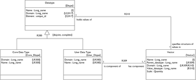
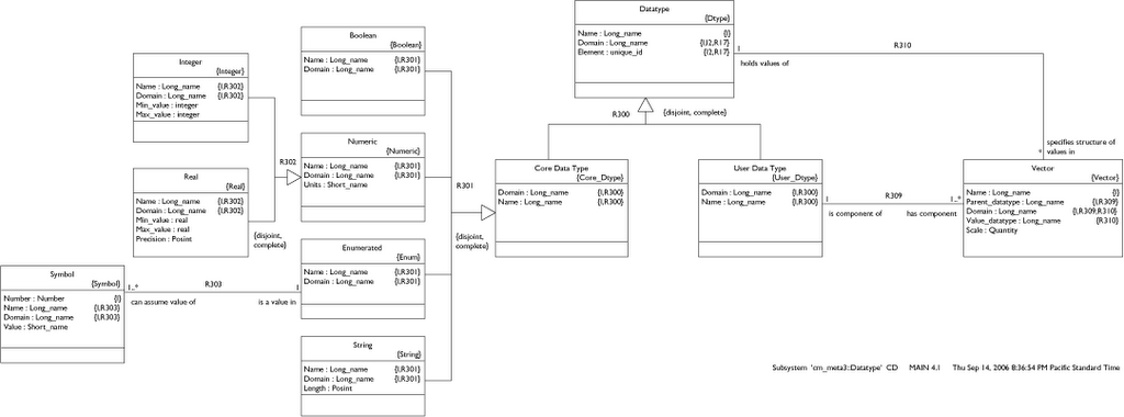
Here I just want to excerpt and explain what I have so far. This is only a model of data type structure, not data type operations. The model is best explained in two pieces: core and user data types. Then I will construct the Position data type to show how the model works.
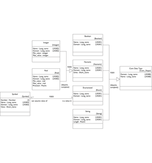
Nothing mysterious here. I have superclassed the Real and Integer Numeric types because they each may specify units.
Note that the max/min values on Integer and Real are kept in the subclasses since the types are not the same. The real type also specifies a precision as a positive integer representing decimal places to the right.
The Enumerated data type consists of a set of Symbols, each of which has a Value.
Finally, String has a positive integer maximum length. Now let's flip over to the right side.
A Vector is simply a collection of one or more values (as determined by Vector.Scale) all specified by the same Datatype. Since the Datatype can be either User or Core we can set up a hierarchical structure. Since Vector.Scale can be 1 or more we can build an N-dimensional matrix at any level of the hierarchy. Let's review the examples mentioned in my earlier post.
First we'll work from the bottom up to define the Position data type. Since minutes and seconds are the same in both latitude and longitude, let's define those.
Name: Minutes
Core Type: Integer
Min_value: 0
Max_value: 59
Units: minutes
So this gives us an instance each of: Integer, Numeric, Core Data Type and Data Type
Seconds: real[0..60] prec 2 units seconds
This gives us an instance each of: Real, Numeric, Core Data Type and Data Type
Unlike thte earlier post I am using negative degrees to avoid defining an enumerated type for [N | S] and [W | E].
No particular reason - just lazy. Also the max Minutes is 59 while max Seconds is 60 (59.999...). Seems like it is better to say "60". Otherwise you end up redundantly specifying the precision with a sequence of trailing nine's.
Latitude and Longitude
Now we start creating User Data Types as we work our way up the hierarchy.
Name: Latitude
Vector: name Degrees, scale 1, value_datatype Lat_Degrees
Vector: name Minutes, scale 1, value_datatype Minutes
Vector: name Seconds, scale 1, value_datatype Seconds
Name: Longitude
Vector: name Degrees, scale 1, value_datatype Long_Degrees
Vector: name Minutes, scale 1, value_datatype Minutes
Vector: name Seconds, scale 1, value_datatype Seconds
For now, I propose the following model be inserted into the datatype subsystem of the * UML metamodel.
If you don't have an image resizer plugin (firefox) the diagrams might be hard to read. I'm new to the blog - writely technology and haven't figured out the easiest way to insert readable model fragments. I will post the full pdf and BridgePoint files on the sourceforge site, though. Probably in a separate file package.
Here I just want to excerpt and explain what I have so far. This is only a model of data type structure, not data type operations. The model is best explained in two pieces: core and user data types. Then I will construct the Position data type to show how the model works.
Core Data Types
First let's examine the left side - the core data types.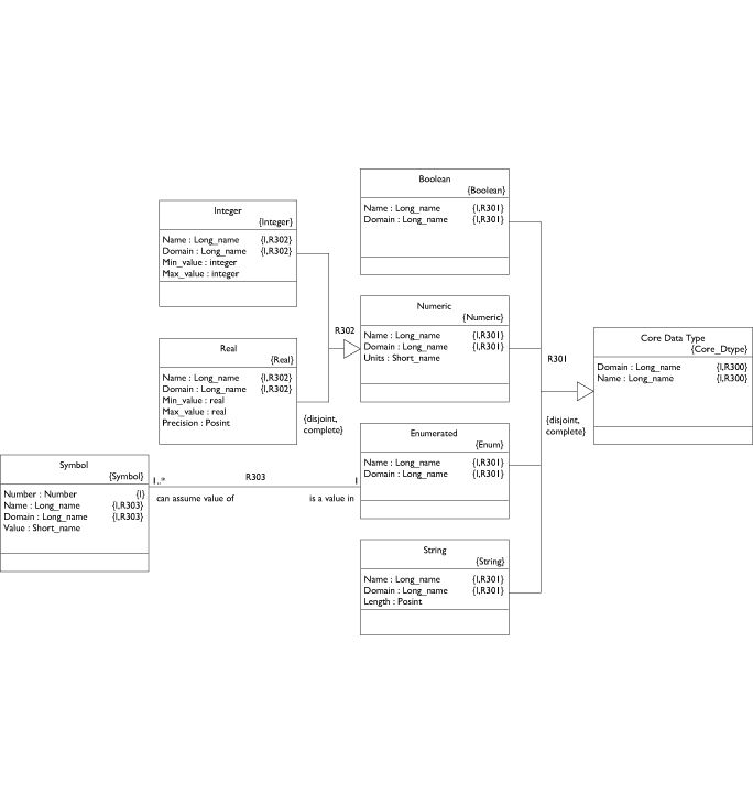
Nothing mysterious here. I have superclassed the Real and Integer Numeric types because they each may specify units.
Note that the max/min values on Integer and Real are kept in the subclasses since the types are not the same. The real type also specifies a precision as a positive integer representing decimal places to the right.
The Enumerated data type consists of a set of Symbols, each of which has a Value.
Finally, String has a positive integer maximum length. Now let's flip over to the right side.
User Data Types
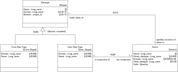
A Vector is simply a collection of one or more values (as determined by Vector.Scale) all specified by the same Datatype. Since the Datatype can be either User or Core we can set up a hierarchical structure. Since Vector.Scale can be 1 or more we can build an N-dimensional matrix at any level of the hierarchy. Let's review the examples mentioned in my earlier post.
First we'll work from the bottom up to define the Position data type. Since minutes and seconds are the same in both latitude and longitude, let's define those.
Minutes
Our specification for Minutes is:Name: Minutes
Core Type: Integer
Min_value: 0
Max_value: 59
Units: minutes
So this gives us an instance each of: Integer, Numeric, Core Data Type and Data Type
Seconds
Using a more compact syntax, we specify:Seconds: real[0..60] prec 2 units seconds
This gives us an instance each of: Real, Numeric, Core Data Type and Data Type
Degrees Latitude
Lat_Degrees: int[-90..90] units degreesDegrees Longitude
Long_Degrees: int[-180..180] units degreesUnlike thte earlier post I am using negative degrees to avoid defining an enumerated type for [N | S] and [W | E].
No particular reason - just lazy. Also the max Minutes is 59 while max Seconds is 60 (59.999...). Seems like it is better to say "60". Otherwise you end up redundantly specifying the precision with a sequence of trailing nine's.
Latitude and Longitude
Now we start creating User Data Types as we work our way up the hierarchy.Name: Latitude
Vector: name Degrees, scale 1, value_datatype Lat_Degrees
Vector: name Minutes, scale 1, value_datatype Minutes
Vector: name Seconds, scale 1, value_datatype Seconds
Name: Longitude
Vector: name Degrees, scale 1, value_datatype Long_Degrees
Vector: name Minutes, scale 1, value_datatype Minutes
Vector: name Seconds, scale 1, value_datatype Seconds
Position
Name: Position
Vector: name Latitude, scale 1, value_datatype Latitude
Vector: name Longitude, scale 1, value_datatype Longitude
Matrix example
Now if, for some reason, we wanted a 5x10 matrix of Position data we could do this:
Name: Position_Column
Vector: name Position, scale 10, value_datatype Position
Name: Position_Matrix
Vector: name Position_Rows, scale 5, value_datatype Position_Column
Moving on
Okay, that's it for now. I might shelve the data type subsystem for a few days while I get some other tasks under control. Namely: Publish up a project roadmap, resume work on the model build script parser, sketch out key parts of the action language subsystem.
Stay tuned!
- Leon
Thursday, September 14, 2006
Data Typing Notes - Part 2
Operations on Core Data Types
Before moving on to the interesting part - application of operations on composite data types - let's take stock of what we already know about how operations are applied to core data types in programming languages.A built in operation may be applied to core data type values using one of three common formats:
- Binary operator
- Unary operator
- Assignment operator
- Function call
We generally see the binary operator format in math expressions like this:
x = 2 + 8
It is rarely done, but we could rephrase the above statement using the function call format: x = add( 2, 8 )
Generically, these formats are:
x = a OP_SYMBOL b
x = OP_NAME( a, b )
x = OP_NAME( a, b )
where a, b are the values and x is the result.
Finally, we have a couple examples of the unary operator format:
++c
-d
-d
Again, we can restate both examples in the function call format:
c = increment( c )
x = negate( d )
x = negate( d )
In addition to the obvious fact that each function has only one input value, we observe that the first example changes the input value while the second does not.
The assignment format modifies the actual value
x *= 2
x OP_ASSIGN a
x = OP_ASSIGN_NAME( x, a )
x OP_ASSIGN a
x = OP_ASSIGN_NAME( x, a )
Okay, let's set those observations aside and take a look at a composite data type and see what kind of trouble we can get ourselves into.
Operations on Composite Data Types
Whenever we create a new composite data type, no matter how simple, we need to review all of the standard operators and consider what functions make sense on the new type. Consider an application where you need to count how many times something occurs. Maybe we have an automotive application and we need to count how many lubrication cycles occur within a given time frame. This sounds like a job for an integer, but not quite. What we need is a counter. It can't ever be negative. Operations-wise we want to increment it, decrement it and reset it to zero. Let's define it.We use a hierarchy format:
Layer : Counter
count : int[0..max]
So we have a data type structure named "Counter". To define our operations we use the OOP mechanism of inheriting the operations already defined in the integer base type with some overriding features. Specifically we want to use the ++ and -- unary operators, but we need to make sure that -- never takes us past 0. Additionally, we need a reset function. Rather than use a hard to read/remember operator we can stick to a function name.
Counter::
op(--) :
if --count < 0, count = 0
op(*) : not defined
op (-) : not defined
op (+) : not defined
reset () : count = 0
if --count < 0, count = 0
op(*) : not defined
op (-) : not defined
op (+) : not defined
reset () : count = 0
Please don't pick apart the syntax above. I'm not trying to nail that down yet! We're really just focusing on the required data. The example above shows that unless otherwise specified, all int operators and functions apply. We show that -- works differently. Some action language will be written in a function to be attached to the -- operator to override normal -- behavior. We turn off the *, - and + operators. We could just leave them on but let's say that we want to tightly define counter behavior. It's a counter and nothing else! A new function is defined for reset. All of this is pretty standard OO inherit and override behavior except that Counter is not an object or a class - it's just a data type in * UML. The distinction will be important and this IS different than OO programming languages.
The binary operation takes two inputs and returns a result without changing either input, so we need to specify a little more:
Compass_Heading::
op(+) :
sum = a + b
if sum == 0:
if sum == 0:
return 0
else:return sum % 360
op(-) :
# insert action language here
op(*) : not defined
In the above psuedo-syntax we use the letters a and b to represent the symbols left and right of the operator. The result to be assigned to the LHS of the expression is "returned". By the way, I am imagining a GUI that displays all operators defined for the core type as check boxes that can easily be flipped to inherit_none or inherit_all. Then the modeler can click the boxes that are exceptions to the rule (inherit or don't inherit). To preclude weird analysis bugs, it is just as important to undefine operators as it is to extend them!
I just had a conversation with my colleague and good friend Andrew Mangogna and realize that I'm starting to confuse my terms regarding hierarchies, layers, matricies, etc. I am going to get this all sorted out by the next post.
Wednesday, September 13, 2006
Data Typing Notes
The term "data type" describes both a structure and a set of operations. Consider the integer data type. Transforming operations such as add, subtract and multiply yield a new integer value. Comparison operations like greater_than, less_than and is_equal_to yield a boolean result.
Analysts rely on two kinds of data types during model development. Core data types and composite data types. Core data types are built in to the modeling language. The analyst can create a composite data type using one or more core data types as building blocks.
What core data types should * UML support? Is the list of core data types bounded by some principle or can you just keep adding them? How are composite data types actually built? How much structure is allowed in a composite data type - is there such a thing as too much? How are composite data types handled by model compilers? How are they handled by an interpreter? These are just a few of the questions that must be answered to construct a useful * UML Data Type metamodel subsystem.
Core Data Types
Since a core data type is built into the modeling language it must be supported by any model compiler. Both the data type structure and all operations should be fully implemented. Keep in mind that a set of models might be translated to Ruby or Java on one day and then directly to Z80 assembler on another. To support all model compilers, we are safer to keep the range of core data types as limited as possible.On the other hand, model developers like to have a wide variety of data types. In fact, real world applications rarely call for a core data type as seemingly ubiquitous as real. Consider an air traffic application. The compass heading data type is not real. It is in fact [0..360] degrees with a precision of, say, .01. The math operations aren't the same either for compass heading. 180.15 + 270.00 = 90.15. Similarly we need distinct data types for altitude, speed and so forth. True, each of these user data types can be tightly or loosely based on the real core data type, but each is different.
So we have a balancing act. To model application requirements independent of any implementation, we want to support lots of user (application level) data types. To support a wide range of model compilers and target languages, we must limit the set of core data types. And right there we have the answer to our problem.
Any user data type must be derivable from core data type building blocks. The model compilers will be concerned only with the core data types. But the modeler will have everything he or she needs to specify whatever application level data types the project demands. Before moving on to how the user builds composite data types, lets first consider the core set.
Consider these proposed core data types:
- boolean
- integer
- real
- enumerated
- string
The first two types, boolean and integer, are supported in every programming language down to assembly level (as far as I know). So they are safe bet. At the level of C and upward, the real (float) data type is supported. Some embedded processors lack floating point capability. But floating point math is quite common in real world applications. In the worst case, a model compiler will have to convert all read core types into integer types during compilation.
Now we move on to enumerated. This is easily implemented using integers so we easily demand this capability of any model compiler.
What about the string data type? C doesn't support strings directly - why should * UML? The data structure is easy enough to accommodate, but there are a number of string operations that must be supported. But strings are extremely common in real world applications. It's hard to imagine avoiding them. That said, certain embedded targets have resource limits that preclude the liberal use of string data types. A model compiler might need to convert string values into a concatenated or compressed integer form to acheive any necessary economy. Since I'm an analyst I have to say "enough for me, let's shift the burden onto the model compiler!" We need strings!
But that's it - we're drawing the line at string. You want to build a model compiler? These are the only types you need to handle. I now assert that the modeler has enough building blocks to construct any required user data type.
Composite Data Types
To build a composite data type we create a Type Specification using one or both of the following layout patterns:- Hierarchy
- Matrix
Hierarchy Layout
Let's say that we want to create the application level Position data type. Hang on - let me bring up Google Earth so I can make sure I get this right... Okay, the Golden Gate Bridge is here:37 48' 59.41" N
122 28' 54.05" W
122 28' 54.05" W
We create a Layer called "Latitude" with four data Cells. The cells are ordered sequentially as:
Layer : Latitude
degrees: int[0..90]
minutes: int[0..60]
seconds: real[0..60] prec 2
pole: enum( N | S )
Each cell refers to a core data type. Each core data type has its own qualifying characteristics.minutes: int[0..60]
seconds: real[0..60] prec 2
pole: enum( N | S )
Layer: Longitude
degrees: int[0..180]
minutes: int[0..60]
seconds: real[0..60] prec 2
meridian: enum( W | E )
It is clear we could have created a lower layer to contain minutes and seconds since they are identical, but let's not worry about that now. We create a top layer for Position and we have a complete Type Specification.minutes: int[0..60]
seconds: real[0..60] prec 2
meridian: enum( W | E )
Layer: Position
Latitude
Longitude
Longitude
It seems that composite data types don't require qualifying characteristics. Is this true? Hmmm.
Matrix Layout
We can also arrange core data type cells in a matrix pattern. To specify a 10x10x2 3D matrix of integers between 1 and 100 where any value is at (x, y, z) we could do this:
Matrix: int[1..100]
x: 10
y: 10
z: 2
y: 10
z: 2
Ah, but what if we wanted to create a 1x5 matrix of Position values for some reason? Then we combine both the Matrix and Hierarchy layout patterns.
Matrix: Position
p: 5
Composite Data Structure Summary
The Hierarchy and Matrix layout mechanisms make it possible to construct composite data types. But it's not enough to define a data type. We need to somehow define the operations specific to that data type.
But I need to get a sandwich right now. So stay tuned for the next post where we will ponder transformation and comparision operators on composite data types and such things.
- Leon
Tuesday, September 12, 2006
Getting Started
Welcome to my * UML blog.

* UML is a set of free (as in beer) UML metamodels and a supporting editor. * UML is a language for building models with the following characteristics:
Executable UML
ISBN: 0201748045
Model Driven Architecture with Executable UML
ISBN: 0521537711
MDA Explained
ISBN: 0201788918
The purpose of this blog is to post technical notes and developments as I construct the * UML editor and accompanying metamodels.
By the way, you can download the current release at SourceForge:
http://sourceforge.net/projects/starruml/
Finally, my company's web page is here:
http://modelint.com
That's all for now.
- Leon
* UML is a set of free (as in beer) UML metamodels and a supporting editor. * UML is a language for building models with the following characteristics:
- Essential application analysis/requirements are kept separate from the implementation mechanics. (I avoided the word "details" here because it is a myth that there are more details in implementation than there are in the application rules. The details just happen to be different).
- All models are fully executable. This means that if you build a * UML model you can say "run" and it will execute just like any program code. Even though the model contains nothing but UML level concepts like classes, attributes, states, and action semantics, the models run without the need for any inserted C, Java, C++, Python or any other alien program language code. Now the models might be running on top of a virtual machine built in one of those languages, but there is no code in the models themselves. This is important because we need to keep the models separate from the implementation.
- All models concepts are expressed in a maximally parallel form. In most programming languages instructions execute in sequence unless parallelism is made explicit with, say, threads or processes/tasks. In * UML it is just the opposite. Everything runs in parallel (on an imaginary massively parallel architecture) and sequence only occurs where explicitly specified. A key benefit of a language like this is that once you build a set of models for an Air Traffic Control Application, for example, you can compile the models to platforms with a variety of parallelism implementation. The same models could be compiled onto a single processor architecture or onto a distributed processor architecture. Same models, different code generation. After all, the application rules don't change - why should the models that formalize those rules change? Only the implementation goo should vary.
- The modeling language itself should be have as few symbols/rules as possible. The less the better. This is because we want the language mechanics to fade into the background with the rules of the application brought to the forefront. The goal of a * UML model is to express the application rules as clearly as possible, in as much detail as possible, without specifying an implementation.
Executable UML
ISBN: 0201748045
Model Driven Architecture with Executable UML
ISBN: 0521537711
MDA Explained
ISBN: 0201788918
The purpose of this blog is to post technical notes and developments as I construct the * UML editor and accompanying metamodels.
By the way, you can download the current release at SourceForge:
http://sourceforge.net/projects/starruml/
Finally, my company's web page is here:
http://modelint.com
That's all for now.
- Leon
Subscribe to:
Posts (Atom)
